Phần mềm lập trinh tự động led quảng cáo tiên tiến
Giới thiệu:
SoftLed là giải pháp phần mềm tiết kiệm nhất cho những người làm
quang báo với biển chữ chạy, biển vẫy,... Các bạn không cần biết lập
trình vi xử lí mà vẫn có thể dễ dàng tạo ra được những hiệu ứng bắt mắt
với SoftLed. Bạn có thể rút ngắn thời gian biến ý tưởng thành sản phẩm,
đồng thời giảm bớt chi phí hàng tháng để thuê 1 hoặc 2 người lập trình.
SoftLed có khả năng tạo ra file HEX dùng để nạp trực tiếp vào vi xử
lí họ MCS51 (8051).
SoftLed có khả năng tạo ra những độ sáng khác nhau trên cùng một
cổng, do đó tạo ra những hiệu ứng mờ dần, sáng dần cực kì ấn tượng mà
thậm chí nhiều người lập trình viên không thể làm được.
Một ưu điểm khác của chức năng này là nó cho phép bạn điều chỉnh
lượng điện năng tiêu thụ trên mạch bằng cách điều chỉnh độ sáng của các
đèn LED, chính vì thế bạn có thể dùng nguồn bé mà vẫn chạy được nhiều
LED nếu giảm cường độ sáng xuống.
SoftLed còn hỗ trợ bạn mô phỏng hiệu ứng một cách chính xác, qua đó
giúp bạn hình dung tốt hơn về hiệu ứng thật khi nạp vào chip.
Link down bản dùng thử:
[You must be registered and logged in to see this link.
http://soundandlightvn.blogspot.com
sưu tầm và biên tập từ nhiều nguồn, mọi ý kiến về kỹ thuật xin vui long liên hệ
soundandlightvn@gmail.com – 0906 715 077 rất mong được đóng góp của các độc giả.
Hiển thị các bài đăng có nhãn ic. Hiển thị tất cả bài đăng
Hiển thị các bài đăng có nhãn ic. Hiển thị tất cả bài đăng
Thứ Sáu, 24 tháng 9, 2010
tông hợp Lập trình C cho VXL - Cơ bản
ác bạn xem tới bài gần cuối đã có bản Pdf toàn bộ tài liệu này do VAGAM thực hiện
Toán tử gán (=). Ex:
c code
1.
2.
b = 5;
3.
a = 2 + b;
4.
a = 2 + (b = 5);
5.
a = b = c = 5;
6.
Các toán tử số học ( +, -, *, /, % )
+ cộng
- trừ
* nhân
/ chia
% lấy phần dư (trong phép chia)
Các toán tử gán phức hợp (+=, -=, *=, /=, %=, >>=, <<=, &=, ^=, |=)value += increase; tương đương với value = value + increase;a -= 5; tương đương với a = a - 5;a /= b; tương đương với a = a / b;price *= units + 1; tương đương với price = price * (units + 1);Tăng và giảmc code 1. ++ c code 1. a++; <=> a+=1; <=> a=a+1; tính chất tiền tố hoặc hậu tố (++a) # (a++) ExB=3;B=3;A=++B;// A is 4, B is 4B=3;A=B++;// A is 3, B is 4Các toán tử quan hệc code 1. ( , !=, >, <, >=, <= )c code 1. 2. Bằng 3. != Khác 4. > Lớn hơn 5. < Nhỏ hơn 6. > = Lớn hơn hoặc bằng 7. < = Nhỏ hơn hoặc bằng 8. EXc code 1. 2. (7 5) sẽ trả giá trị false 3. (6 >= 6) sẽ trả giá trị true tất nhiên thay vì sử dụng các số, chúng ta có thể sử dụng bất cứ biểu thức nào. Cho a=2, b=3 và c=6c code 1. 2. (a*b >= c) sẽ trả giá trị true. 3. (b+4 < a*c) sẽ trả giá trị false 4. Chú ý rằng = (một dấu bằng) lf hoàn toàn khác vớic code 1.(hai dấu bằng). (c code 1.) nhằm so sánh còn (=)gán giá trị của biểu thức bên phải cho biến ở bên trái .Các toán tử logic ( !, &&, || ).! NOT&& AND|| OREX:(3 > 6)) trả về true ( true code
1.
2.
!(5 5) trả về false vì biểu thức bên phải (5 5) có giá trị true.
3.
!(6 <= 4) trả về true vì (6 <= 4)có giá trị false. 4. !true trả về false. 5. !false trả về true. 6. ( (5 5) && (3 > 6) ) trả về false ( true && false ).
7.
( (5 5)
Các toán tử thao tác bit ( &, |, ^, ~, <<, >> ).
& AND Logical AND
| OR Logical OR
^ XOR Logical exclusive OR
~ NOT Đảo ngược bit
<< SHL Dịch bit sang trái>> SHR Dịch bit sang phải
Thứ tự ưu tiên của các toán tử
Toán tử logic Trái
11 ?: Toán tử điều kiện Phải
12 = += -= *= /= %=
>>= <<= &= ^= |= Toán tử gán Phải13 , Dấu phẩy Tráicode 1. 2. 1 :: scope Trái 3. 2 () [ ] -> . sizeof Trái
4.
3 ++ tăng/giảm Phải
5.
~ Đảo ngược bit
6.
! NOT
7.
& * Toán tử con trỏ
8.
(type) Chuyển đổi kiểu
9.
+ - Dương hoặc âm
10.
4 * / % Toán tử số học Trái
11.
5 + - Toán tử số học Trái
12.
6 << >> Dịch bit Trái
13.
7 < <= > >= Toán tử quan hệ Trái
14.
8 != Toán tử quan hệ Trái
15.
9 & ^ | Toán tử thao tác bit Trái
16.
10 &&
giotdang1985@yahoo.com
thtam | 11:00:18 05-08-07 | Posts: 23 2
Kiến thức C cơ bản dùng lập trình VXL
kiến thức này rất cần cho những người như tôi, chỉ quen dùng asm và bascom.
mong bạn tiếp tục viết các kiến thức C mà bạn đã dùng cho vi điều khiển?
Bạn có thể nói qua khoảng bao nhiêu lệnh C và nhiều ko vậy?
Nếu học thì tốn khoản nhiều thời gian không bạn? có thể bắt đầu bằng các bài nào vậy?
Chúc bạn luôn vui!
Nothing is not possible!!!
I am doing and it will be done by me!
thật tuyệt vời, em xin hỏi cách viết 1 delay trong C cho mọi vi điều khiển là thế nào ạ?
Em ví dụ sau nhé:
Bài toán kiểm tra relay, nếu thay đổi vị trí relay thì mở động cơ lên.
box code
1.
org
2.
3.
dc_cong_tac euq bit 1.0
4.
5.
relay euq bit 1.1
6.
7.
main
8.
9.
abc: // Nhản
10.
djnz relay, 0 // kiem tra trang thay relay co ở mức thấp ko
11.
lmp: abc //quay lại nhản nếu relay chưa đổi trạng thái
12.
set dc_cong_tac // bật động cơ để mở công tắc (công tắc đèn chẳng hạn)
13.
14.
ret
(Lâu quá em ko viết lại ASM, có gì nhờ anh trietnguyen chỉ giúp lại chỗ sai)
Vậy chyển qua C thì thế nào ạ? thanks các anh
mitvn@gmail.com
Một ngày mitvn sẽ giỏi lập trình!
Ai có câu hỏi gì về C, và matlab cứ viết lên để giúp tôi tiến bộ hơn với nhé!
Writing C Code for the 8051
Interrupt : Vector address ; Interrupt number
External0 0003h 0
Timer0 000Bh 1
External1 0013h 2
Timer 1 001Bh 3
Serial 0023h 4
c code
1.
2.
org 00h
3.
ljmp main
4.
org 0003h
5.
ljmp ngat0
6.
org 30h
7.
8.
main:
9.
...
10.
Here: sjmp Here
11.
12.
ngat0:
13.
...
14.
reti
code C
box code
1.
2.
void main
3.
{
4.
...
5.
while(1)
6.
}
7.
void ngat0(void) interrupt 0
8.
{
9.
...
10.
}
Chào bạn,
. Keil C và Codevison tuy cùng dùng C khác nhau ở các lệnh hỗ trợ cho từng loại vđk. Đó tạo ra nét riêng của từng trình biên dịch, cái nào mạnh hơn cái nào một phần cũng là do vậy.
. Về C trong Keil: chẳng hạn kiểu dữ liệu bit, sbit, sfr.. chỉ gọi là C của Keil thôi. còn cấu trúc while.. là C chuẩn. những kiểu dữ liệu đó của riêng từng trình biên dịch, nhà sx quy định.
Ngoài ra Keil còn chứa các lệnh hỗ trợ dành riêng cho vđk, chẳng hạn lệnh
c code
1.
_crol_, _cror_
hoặc trong Bascom có lệnh
c code
1.
lcd, wait..v.v
, đó có thể gọi là lệnh hỗ trợ rồi còn gì biggrin
. Pinnacle dùng Asm, do vậy mình mà mình chỉ nhắc đến ngôn ngữ bậc cao thôi, đó là C và Basic, chắc do bạn đọc k kĩ smile
Chúc thành công !
Nơi nào có ý chí, nơi đó có con đường.
ý bạn thanlan nói dĩ nhiên là cách viết của Keil C rồi (luồng này đang viết về Keil C mà). mà bạn thanlan nói đúng rồi đấy, k hiểu sao bạn giotdang lại viết như vậy nhỉ ?
. chào mitvn, bạn thích học trên diễn đàn là điều rất đáng hoan nghênh, vì đó cũng là một cách học. chính mình cũng bắt đầu học như bạn đây.
. Nhưng muốn theo dõi luồng này tốt, bạn cần có kiến thức căn bản về C. Vì luồng này là "C cho vđk" nên bạn giotdang viết khá vắn tắt về C, chủ yếu là ôn lại thôi sau đó tập trung vào lập trình C cho vđk, trước mắt là 8051. tương tự, bạn ấy cũng không trình bày chi tiết về vdk, nên bạn sẽ thấy rất nhiều thắc mắc, mơ hồ là vậy. Vì thế mình mới khuyên bạn đọc trước về phần cứng vdk và C căn bản là thế.
. Bạn yên tâm đi, 8051 hay AVR hay PIC chung qui lại cũng là vdk 8bit, nên lập trình C cũng không khác nhau mấy. Bạn cứ ôn lại rồi theo dõi luồng này sẽ thấy rất bổ ích đấy ! wink
. Chúng ta thảo luận để cùng nhau tiến bộ mà, vì vậy nếu khi tìm hiểu gặp thắc mắc mình sẽ mở ra luồng mới về "C căn bản" hoặc "tìm hiểu về vdk" chẳng hạn, okie ? wink
AVR
Đây là bài đầu tiên của loạt bài về AVR. Sau khi kết thúc bài đầu tiên bạn dễ dàng lập trinh input và output cho AVR
Tóm tắt : Lập trình điều khiển led bật tắt ,sử dụng cách định nghĩa PIN và PORT ,cách dùng thư viện delay.h của codevision.
Giới thiệu:
Cấu trúc chân của AVR có thể phân biệt rõ chức năng (vào ra) trạng thái (0 1) từ đó ta có 4 kiểu vào ra cho một chân của avr.Khác với 89 là chỉ có 2 trạng thái duy nhất (0 1) . Đặc biệt nguồn từ chân của AVR đủ khoẻ để điều khiển Led trực tiếp (mA) còn 89 chỉ là vài uA .
Để điều khiển các chân này chúng ta có 2 thanh ghi
->PORTx :giá trị tại từng chân (0 – 1) có thể truy cập tới từng bit PORTx.n
->DDRx : thanh ghi chỉ trạng thái của từng chân , vào hoặc là ra .Giá trị 1 là ra và 0 là vào .
Ví dụ 1 : Nhấp nháy lần lượt đèn xanh và đèn đỏ , khi ấn nút bấm chỉ có đèn đỏ sáng.
Phần cứng : đèn xanh PORTB.4 , đèn đỏ PORTB.5 , nút bấm PINB.7
Chú ý :
định nghĩa 1 chân là chân vào PIN x.x
#define nut_bam PINB.7
định nghĩa 1 chân là chân vào PORT x.x
#define den_do PORTB.5
Trong bài này PORT B có 2 biến đầu ra là PB5 và PB6
DDRB=0b00110000 =0x30
Khởi tạo chân PB7 cần được treo lên 5V , khi ấn nút bấm sẽ thông GND(0V) nên ta có PORTB=0b10000000=0x80;
Sau khi định nghĩa , nếu bạn den_do=1; đèn led đỏ sẽ tắt
den_do=0; đèn sẽ sáng .
( do cách thiết kế mạch đầu dương led nối 5V còn đầu âm nối vào VĐK)
delay.h có 2 cách gọi là trễ theo ms và us
delay_ms(time);
delay_us(time);
c code
1.
2.
/*****************************************************
3.
This program was produced by the
4.
CodeWizardAVR V1.24.8d Professional
5.
Automatic Program Generator
6.
© Copyright 1998-2006 Pavel Haiduc, HP InfoTech s.r.l.
7.
http://www.hpinfotech.com
8.
9.
Project :
10.
Version :
11.
Date : 12/27/2007
12.
Author : LENGOCTUAN
13.
Company : VAGAM
14.
Comments:
15.
16.
17.
Chip type : ATmega16
18.
Program type : Application
19.
Clock frequency : 8.000000 MHz
20.
Memory model : Small
21.
External SRAM size : 0
22.
Data Stack size : 256
23.
*****************************************************/
24.
25.
#include
26.
#include
27.
28.
// Declare your global variables here
29.
30.
#define den_xanh PORTB.5
31.
#define den_do PORTB.6
32.
#define nut_bam PINB.7
33.
34.
void main(void)
35.
{
36.
37.
// Port B initialization
38.
// Func7=In Func6=Out Func5=Out Func4=In Func3=In Func2=In Func1=In Func0=In
39.
// State7=T State6=0 State5=0 State4=T State3=T State2=T State1=T State0=T
40.
PORTB=0x80;
41.
DDRB=0x30;
42.
43.
44.
45.
while (1)
46.
{
47.
// Place your code here
48.
//khi nut bam chua duoc bam logic nut_bam=1
49.
if(nut_bam)
50.
{
51.
den_xanh=1;den_do=0;
52.
delay_ms(500);
53.
den_xanh=0;den_do=1;
54.
delay_ms(500);
55.
}
56.
//khi nut bam duoc an nut_bam=0 chi den do sang
57.
else
58.
{den_xanh=1;den_do=0;}
59.
};
60.
}
61.
62.
63.
Bạn gặp phải vấn đề dội nút nhấn. Điều gì xảy ra khi bạn nhấn nút ?
- Đặc tính dội: Thời gian dội nút từ 10ms đến 50ms (tùy loại nút)
Từ giản đồ, suy nghĩ hồi lâu wink , người ta nghĩ ra chiến thuật chống lại hiện tượng này:
Lưu đồ của bài toán bạn đặt ra như sau:
Mạch đèn giao thông bị lỗi khi reset IC đếm Read more: http://www.ant7.com/forum/forum_posts.asp?TID=8528&get=last#16864#ixzz10SXHa400
Tôi thiết kê mạch kiểu như sau :
-- 2 con 74192 kết nối với led để đếm giây
-- 2 con 4017 (con thứ 2 không có tác dụng ) đếm đến 70 con này để canh thời gian reset 2 con 74192 trên !
-- thời gian cho các đèn là xanh 30- vàng 5- đỏ 35
-- có 3 lần reset 74192 là: lúc 30 - lúc 35 - lúc 70
mình không hiểu sao 2 lần đầu là lúc 30, 35 thì đúng reset tốt. sau đó nó đếm 3s và reset kì lạ hơn là chân MR=0 ( đáng lẽ là không reset ) ! trong bài mình chỉ cho MR nối với một cổng OR 4 lối vào nên mãi vẫn không hiểu tại sao MR =0 mà nó reset được cả !
Click vào hình để xem ở kích thước nguyên gốc
Read more: http://www.ant7.com/forum/forum_posts.asp?TID=8528&get=last#16864#ixzz10SXA2CCy
keil C Programming Tutorial: Functions
Keil C compiler provides number of extensions for standarad C function declerations. These extensions allows you to:
- Specify a function as an interrupt procedure
- Choose the register bank used
- Select memory model
►Function Declaration:
[Return_type] Fucntion_name ( [Arguments] ) [Memory_model] [reentrant] [interrupt n] [using n]
Return_type: The type of value returned from the function. If return type of a function is not specified, int is assumed by default.
Function_name: Name of function.
Arguments: Arguments passed to function.
Options:
These are options that you can specify along with function declaration.
Memory_model: explicit memory model (Large, Compact, Small) for the function. Example:
CODE:
int add_number (int a, int b) Large
reentrant: To indicate if the function is reentrant or recursive. This option is explained later in the tutorial.
interrupt: Indicates that function is an interrupt service routine. This option is explained later in the tutorial.
using: Specify register bank to be used during function execution. We have three register banks in 8051 architecture. These register banks are specified using number 0 for Bank 0 to 3 for Bank 3 as shown in example
CODE:
void function_name () using 2{ //function uses Bank 2
//function code
}
//function code
}
►Interrupt Service Routines:
A function can be specified as an interrupt service routine using the keyword interrupt and interrupt number. The interrupt number indicates the interrupt for which the function is declared as service routine.
Following table describes the default interrupts:
As 8051 vendors create new parts, more interrupts are added. Keil C51 compiler supports interrupt functions for 32 interrupts (0-31). Use the interrupt vector address in the following table to determine the interrupt number.
The interrupt function can be declared as follows:
CODE:
void isr_name (void) interrupt 2 {
// Interrupt routine code
}
// Interrupt routine code
}
Please make sure that interrupt service routines should not have any arguments or return type except void.
►Reentrant Functions:
In ANSI C we have recursive function, to meet the same requirement in embedded C, we have reentrant function. These functions can be called recursively and can be called simultaneously by two or more processes.
Now you might be thinking, why special definition for recursive functions?
Well you must know how these functions work when they are called recursively. when a function is running there is some runtime data associated with it, like local variables associated with it etc. when the same function called recursively or two process calls same function, CPU has to maintain the state of function along with its local variables.
Reentrant functions can be defined as follows:
CODE:
void function_name (int argument) reentrant {
//function code
}
//function code
}
Each reentrant function has reentrant stack associated with it, which is defined by startup.A51 file. Reentrant stack area is simulated internal or external memory depending upon the memory model used:
- Small model reentrant functions simulate reentrant stack in idata memory.
- Compant model reentrant functions simulate reentrant stack in pdata memory.
- Large model reentrant functions simulate reentrant stack in xdata memory.
►Real-time Function Tasks:
Keil or C51 provides support for real-time operating system (RTOS) RTX51 Full and RTX51 Tiny. Real-time function task are declared using _task_ and _priority_ keywords. The _task_ defines a function as real-time task. The _priority_ keyword specify the priority of task.
Fucntions are declared as follows:
CODE:
void func (void) _task_ Number _priority_ Priority {
//code
}
//code
}
where:
Number: is task ID from 0 to 255 for RTX51 Full and 0 to 15 for RTX51 Tiny.
Priority: is priority of task.
Real-time task functions must be declared with void return type and void argument list (say no arguments passed to task function).
►Basic of a C program
As we already discussed, Keil C is not much different from a normal C program. If you know assembly, writing a C program is not a problem, only thing you have to keep in mind is forget your controller has general purpose registers, accumulators or whatever. But do not forget about Ports and other on chip peripherals and related registers to them.
In basic C, all programs have atleast one function which is entry point for your application that function is named as "main" function. Similarly in keil, we will have a main function, in which all your application specific work will be defined. Lets move further deep into the working of applications and programs.
When you run your C programs in your PC or computer, you run them as a child program or process to your Operating System so when you exit your programs (exits main function of program) you come back to operating system. Whereas in case of embedded C, you do not have any operating system running in there. So you have to make sure that your program or main file should never exit. This can be done with the help of simple while(1) or for(;;) loop as they are going to run infinitely. Following layout provides a skeleton of Basic C program.
CODE:
void main(){
//Your one time initialization code will come here
while(1){
//while 1 loop
//This loop will have all your application code
//which will run infinitely
}
}
//Your one time initialization code will come here
while(1){
//while 1 loop
//This loop will have all your application code
//which will run infinitely
}
}
When we are working on controller specific code, then we need to add header file for that controller. I am considering you have already gone through "Keil Microvision" tutorial. After project is created, add the C file to project. Now first thing you have to do is adding the header file. All you have to do is right click in editor window, it will show you correct header file for your project.
Figure below shows the windows context for adding header file to your c file.
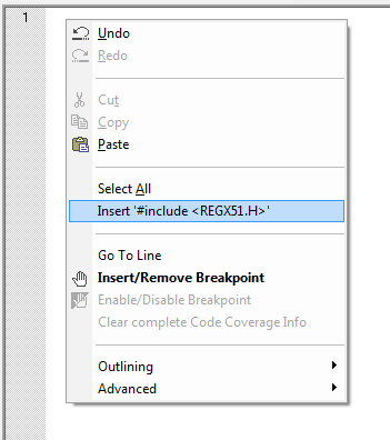
►Writing Hardware specific code
In harware specific code, we use hardware peripherals like ports, timers and uart etc. Do not forget to add header file for controller you are using, otherwise you will not be able to access registers related to peripherals.
Lets write a simple code to Blink LED on Port1, Pin1.
CODE:
#include //header file for 89C51
void main(){
//main function starts
unsigned int i;
//Initializing Port1 pin1
P1_1 = 0; //Make Pin1 o/p
while(1){
//Infinite loop main application
//comes here
for(i=0;i<1000;i++)
; //delay loop
P1_1 = ~P1_1;
//complement Port1.1
//this will blink LED connected on Port1.1
}
}
void main(){
//main function starts
unsigned int i;
//Initializing Port1 pin1
P1_1 = 0; //Make Pin1 o/p
while(1){
//Infinite loop main application
//comes here
for(i=0;i<1000;i++)
; //delay loop
P1_1 = ~P1_1;
//complement Port1.1
//this will blink LED connected on Port1.1
}
}
You can now try out more programs. "Practice makes a man perfect".
In next section of this tutorial, we will learn how to mix C and assembly codes.
►Interfacing C program to Assembler
You can easily interface your programs to routines written in 8051 Assembler. All you need to do is follow few programming rules, you can call assembly routines from C and vice-versa. Public variables declared in assembly modules are available to your C program.
There maybe several reasons to call an assembly routine like faster execution of program, accessing SFRs directly using assembly etc. In this part of tutorial we will discuss how to write assembly progarms that can be directly interfaced with C programs.
For any assembly routine to be called from C program, you must know how to pass parameters or arguements to fucntion and get return values from a function.
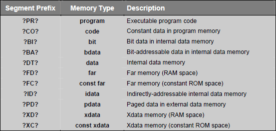
►Segment naming
C51 compiler generates objects for every program like program code, program data and constant data. These objects are stored in segments which are units of code or data memory. Segment naming is standard for C51 compiler, so every assembly program need to follow this convention.
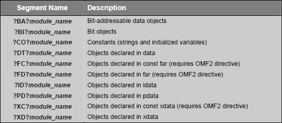
Segment names include module_name which is the name of the source file in which the object is declared. Each segment has a prefix that corresponds to memory type used for the segment. Prefix is enclosed in question marks (?). The following is the list of the standard segment name prefixes:
►Data Objects:
Data objects are the variables and constants you declare in your C programs. The C51 compiler generates a saperate segment for each memory type for which variable is declared. The following table lists the segment names generated for different variable data objects.
►Program Objects:
Program onjects includes code generated for C programs functions by C51 compiler. Each function in a source module is assigned a separate code segment using the ?PR?function_name?module_name naming convention. For example, for a function name send_char in file name uart.c will have a segment name of ?PR?SEND_CHAR?UART.
C51 compiler creates saperate segments for local variables that are declared within the body of a function. Segment naming conventions for different memory models are given in following tables:
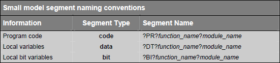
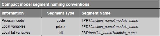
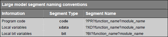
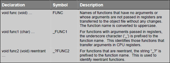
Function names are modified slightly depending on type of function (functions without arguments, functions with arguments and reentrant functions). Following tables explains the segment names:
In next section we will learn regarding defining functions which can be called from any C function and how a C function can be called from assembly.
►Function Parameters
C51 make use of registers and memory locations for passing parameters. By default C function pass up to three parameters in registers and further parameters are passed in fixed memory locations. You can disable parameter passing in register using NOREGPARMS keyword. Parameters are passed in fixed memory location if parameter passing in register is disabled or if there are too many parameters to fit in registers.
►Parameter passing in registers
C functions may pass parameter in registers and fixed memory locations. Following table gives an idea how registers are user for parameter passing.
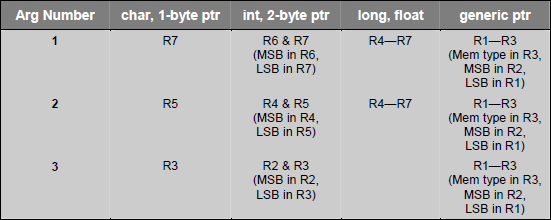
Following example explains a little more clearly the parameter passing technique:
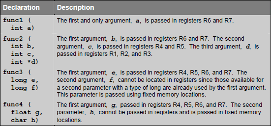
►Parameter passing in Fixed Memory Locations
Parameters passed to assembly routines in fixed memory lcoation use segments named
?function_name?BYTE : All except bit parameters are defined in this segment.
?function_name?BIT : Bit parameters are defined in this segment.
All parameters are assigned in this space even if they are passed using registers. Parameters are stored in the order in which they are declared in each respective segment.
The fixed memory locations used for parameters passing may be in internal data memory or external data memory depending upon the memory model used. The SMALL memory model is the most efficient and uses internal data memory for parameter segment. The COMPACT and LARGE models use external data memory for the parameter passing segments.
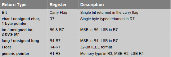
►Fucntion Return Values
Function return values are always passed using CPU registers. The following table lists the possible return types and the registers used for each.
►Example
Following example shows how these segment and function decleration is done in assembler.
CODE:
;Assembly program example which is compatible
;and called from any C program
;lets say asm_test.asm is file name
name asm_test
;We are going to write a function
;add which can be used in c programs as
; unsigned long add(unsigned long, unsigned long);
; as we are passing arguments to function
;so function name is prefixed with '_' (underscore)
;code segment for function "add"
?PR?_add?asm_test segment code
;data segment for function "add"
?DT?_add?asm_test segment data
;let other function use this data space for passing variables
public ?_add?BYTE
;make function public or accessible to everyone
public _add
;define the data segment for function add
rseg ?DT?_add?asm_test
?_add?BYTE:
parm1: DS 4 ;First Parameter
parm2: ds 4 ;Second Parameter
;either you can use parm1 for reading passed value as shown below
;or directly use registers used to pass the value.
rseg ?PR?_add?asm_test
_add:
;reading first argument
mov parm1+3,r7
mov parm1+2,r6
mov parm1+1,r5
mov parm1,r4
;param2 is stored in fixed location given by param2
;now adding two variables
mov a,parm2+3
add a,parm1+3
;after addition of LSB, move it to r7(LSB return register for Long)
mov r7,a
mov a,parm2+2
addc a,parm1+2
;store second LSB
mov r6,a
mov a,parm2+1
addc a,parm1+1
;store second MSB
mov r5,a
mov a,parm2
addc a,parm1
;store MSB of result and return
;keil will automatically store it to
;varable reading the resturn value
mov r4,a
ret
end
Now calling this above function from a C program is very simple. We make function call as normal function as shown below:
CODE:
extern unsigned long add(unsigned long, unsigned long);
void main(){
unsigned long a;
a = add(10,30);
//a will have 40 after execution
while(1);
}
void main(){
unsigned long a;
a = add(10,30);
//a will have 40 after execution
while(1);
}
sưu tầm và biên tập từ nhiều nguồn, mọi ý kiến về kỹ thuật xin vui long liên hệ
soundandlightvn@gmail.com – 0906 715 077 rất mong được đóng góp của các độc giả.
Easy-DownloaderV1.1 forATMEL 89C2051/4051
Build your own a personal writer forprogramming HEX code into Flash based microcontroller AT89C2051(2k) andAT89C4051(4k). Simple hardware and Easy use software in DOS and Windowversion. Single-side and double side PCB files included.sourcecode with sdcc version!
Introduction
The first version of the Easy-Downloaderwas designed in 1997 to be used as a tool for my students on building her/hisown microcontrollers circuit in the class " Designing Microprocessors System".The circuit features low-cost and easy use. The latest version V1.1 wasdesigned to be used with 2051 and the newest 4051 chips. There is no separatefunctions like other programmer e.g., blank check, erase, write. Simplytype say, c:\..>ez hello , the hex file "hello.hex" will then be programmedto the chip automatically. If the chip is not blank or the code is locked,it will erase first, then write and verify... that all.
Hardware
Figure 1 shows a circuit diagramof the Easy-Downloader. As shown, the circuit uses a 89C2051 with writer.hexfirmware, 74LS373 8-bit latch, DS275-like, 7805, LM317 and two transistors,2N2222A and 2N2907A. The programming voltage control circuit is the sameas recommended by ATMEL application note. It can be raised from 0V, 5Vand 12V by appropriated signal from P3. The 8-bit latch, 74LS373 providessome signal for selecting the programming modes. A byte to be programmedor read back is sent/received through P1. Incrementing address is doneby pulsing a positive pulse to XTAL pin. The circuit may be built usingsimple point-to-point soldering with a general purpose PCB( fish's egglike PCB) or making PCB shown above, the file is Easy-v1.pcbProtel PCB version 2.76. The finished board should be tested without anychips; 1) +5V supply, 2) programming voltage 0V, 5V and 12V by connectingthe pin that control (P3.5 and D) 2N2222A and 2N2907 to +5V and/or GND.The adapter output should be approx. 15Vdc 100mA.
Figure1: Circuit Diagram of Easy-Downloader V1.1
AcrobatPCB Files
Assuggested by a friend from Romania, Puiu Chiselita, to provide PCB imagein Acrobat file, so I have asked my friend, Jaroon Keawkhrua. He made withinan hour, thanks again for providing us, the Acrobat PCB file.
TOPLAYER (80kB) easy-v2t.pdf
BOTTOMLAYER (36kB) easy-v2b.pdf
COMPONENTLAYER (51kB) easy-v2o.pdf
Software
Two files that you shouldget are: writer.hex 4,871 bytes, the intelhex file firmware for 89C2051 chip ( the actual code size is 2021 bytes)and, ez.exe 20,800 bytes the uploader programrun on PC, send hex file to the downloader. The original writer.cprogram was written in 'C'. To modify, it needs Micro C-compiler from DunfieldDevelopment System Ontario Canada with tiny memory model.
Functional Test
Use a given programmer (or readymade Easy-Downloader) write the writer.hex into the 2051 chip. Put theprogrammed 2051 chip to the board. Invoke any communication software with9600 baud, 8-data bit, no parity. Connect DB-9 to COM1, say, press enterkey, the title "Easy-Downloader V1.1 for ATMEL 89C2051/4051" would be appearedon the screen. type >s2048 ( set byte counter to 2k), then without the2051 chip in ZIF, type >r (read 2kB), on screen would show FFFFFFFFFFF...indicating corrected wiring for P1. If you put the chip having alreadyprogram inside, r command will show the hex code with the number of byteset by s command. Try e command to erase the entire program!! All done.Figure 2 shows example of using Xtalk program to test the board.
Figure2: Using Xtalk to test the board
Now try with "ez"the uploader program to help you more easy to write the hex file to thechip. Example of using ez is shown in Figure 3. Have fun...
Note: EZ3 can use only withold PC that runs dos, for new PC try with window version!
Figure3: Example of using EZ program writes the writer.hex to 2051 chip
Figure4: Example of Using EZ3 and EZ3.1
DownloadEZUploader V3.0 for Window The EZ Uploader provides a simplemeans of sending HEX file to the writer board. To connect the board withEZ, click available COM port, COM1, say. After the EZ recognizes the chips,then click Send Hexfile, that all. Since there is no signature byte thatindicates chip number and programming voltage, thus you have to choosethe appropriated memory size either 2051 or 4051 manually, i.e., 2048 or 4096 respectively.
DownloadEZUploader V3.1 for Window An upgraded version of EZ3with RAED and SAVE AS features for reading HEX code resided in the chipandsave as an Intel HEX file.
Tips
HEX fileextension
Some Assembler or Compiler produceoutput hex file with .OBJ instead of .HEX. The EZ needs .HEX extension,just rename it...
ExpensiveZIF Socket
Without expensive ZIF socket,you may use an ordinary socket instead, surely many times of pulling thechips may cause the far end leg of the 2051 chip broken. My student suggestsme to insert one more socket to the 2051 chip. It works very nice. Eventhe programmer has ZIF, but your application board does not have. Betterto insert one socket to strengthen the 2051's leg.
DC Adapter
Any DC adapters, fixed or adjustablecan be used, a bridge diode corrects polarity for the regulator IC eventually.Many adapters provide higher DC output than the value labeled, to ensure,check the proper programming voltage that must be in the range of 11.5to 12.5V.
Put theRight Position
The latest version does notinclude the protection circuit if putting wrong position, i.e., GND-Vcc<--> Vcc-GND.
Thus before put the chipinto the programmer or your application board, back to see your thought,say I am putting the 2051 chip to the right position, then pick the chip,and place it...
89C1051
There is no problem with 89C1051chip but ensure that the hex code size must less than 1024 bytes (000Hto 3FFH). While verifying after erase it showed 0 to 2048 byte as the 2051chip, it means twice reading, i.e., 000H-3FFH then 000H-3FFH, the samephysical address. When programming, the control chip will write and verifyonly the size of program.
Easy 1.1 Links
* MakeYour Own Single-Side PCB for Easy-Downloader V1.1
* RS232CLevel Converter A circuit for RS232C level converter, MAX232and DS275.
* Experimentingthe 2051 with C Programming
Sourcecode for sdcc
I spent my weekend modifiedthe source code of Easy downloader V1.1 for sdcc! Now you may study thecode to see how it works with a nice tool available freely for everyone,the small device c compiler, sdcc. The compiled code is very nice and isvery compact. You may noticed that the size of new firmware is only 1128bytes!
Download the source code,WRITER1.C, hex file, writer1.hex and the compiler,SDCC.zip
Below is a sample how touse sdcc.
C:\sdcc\app>s
C:\sdcc\app>path=c:\sdcc\bin
C:\sdcc\app>sdcc writer1.c
library file /sdcc/share/sdcc/lib/small/libsdcc.lib
library file /sdcc/share/sdcc/lib/small/libint.lib
library file /sdcc/share/sdcc/lib/small/liblong.lib
library file /sdcc/share/sdcc/lib/small/libfloat.lib
C:\sdcc\app>packihx writer1.ihx>writer1.hex
packihx: read 166 lines, wrote 75:OK.
C:\sdcc\app>
The batch file s.bat contains,
path=c:\sdcc\bin
sdcc writer1.c
packihx writer1.ihx>writer1.hex
The output machine code ishex file with *.ihx extension. We can use a tool, packihx to convert suchhex file with *.ihx to *.hex easily.
The ez4.1 is suitable forprogramming the hex file into a 20-pin microcontrollers, 89C2051/4051.Since the hex file produced by sdcc is not sorted from low address to highaddress. The old version, EZ31 has bug for such hex file. So I recommenedto use EZ4.1 for program loading. Click at the picture to download EZ4.1!
Contributionto Easy Programmer V1.1
* PROGRAMM.PCB Layout made by Hooman Falahati , from IRAN.
Đăng ký:
Bài đăng (Atom)